Registruj se
Prijavi se
TRANSFORMER OIL FILTRATION MACHINE - S 250
KONDIC Oil Filtration


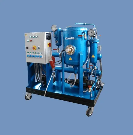
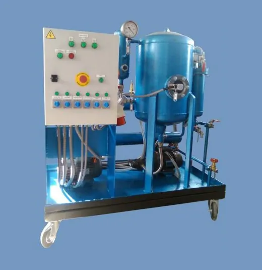
TRANSFORMER OIL FILTERING, DEGASSING AND DRYING MACHINE MODEL S 250
SPECIFICATION
Maximal oil flow rate 250 lit / h
Heating capacity 2 / 4 kW
Adjustable oil temperature range 45 °C – 100 °C
Differential temperature (inlet/outlet) approx. 28 °C
Minimal oil inlet temperature 5 °C
Vacuum pump capacity 10 m3/h
Filter fineness 1-5 microns
Total power 5 kW
Final oil qualities, after three passes:
- water content 2 - 5 ppm
- gas content 0.05 % Vol
Operating pressure in degassing tank 2 - 9 mbar
Machine, size: cca.1100 mm x 650 mm
x H = 1250mm
Machine, weight approx. 120 kg
Above mentioned values after conditioning are guaranteed when treating naphtenic based mineral oils with
normal foaming conditions.
The Machine is delivered ready for operation, together with:
- control panel, wiring, two connecting hoses for oil (each 5 m long) and safety
devices which provides maximum operating security;
- specially designed system in the degassing tank which provides uniform
distribution of the processed oil in the low-pressure environment, in order to
achieve best treatment results;
- spare filter cartridge with 3 micron fineness;
- spare heating element;
BRIEFLY ABOUT THE MACHINE
The Machine S 250 is designed for filtering, drying and degassing of transformer oil.
The model and the example that were kept in mind during development and construction of this Machine were the
machines, which proved to be most efficient in operation, built by leading European manufacturers.
All essential parts of the Machine (vacuum pump, gear pump, electromagnetic valve and floater) are produced by
leading German manufacturers. Some of the components (such as fine and coarse filters, temperature control,
construction of the heaters, gear pump) had to be modified to improve the operation of the Machine and to eliminate
shortcomings noticed in the operation of some other machines of this kind.
BRIEFLY ABOUT THE PROCESS
The electrical properties of insulating oil (such as puncture voltage and coefficient of losses) can be considerably
improved by its filtering, degassing and dehydration. Only properly and sufficiently filtered and dried oil is suitable
for filling up of the transformer. Even brand-new oil is rarely clean enough to be used in high-voltage installations,
as it is often already polluted in the transporting barrels and it may absorb too much moisture in contact with air.
During its operation, transformer-insulating oil is absorbing moisture over its free surface in the expansion vessel
and it becomes polluted by absorbing dirty particles, fibers, soot and aging products. Therefore, oil conditioning
has to eliminate the following:
- solid particles
- free and dissolved water
- dissolved gasses
The puncture voltage can be considerably increased and the coefficient of loses tangδ improved by filtering,
degassing and dehydration of insulating oil to the extent depending on moisture content.
THE MACHINE CONSISTS OF:
1. Inlet valve a spherical valve 1/2“ with special “Teflon” gaskets
2. Coarse filter as oil is often very polluted, the Machine is fitted with a large sized, easy to open and clean, coarse
filter. Oil is conveyed at a reduced flow rate around a strong permanent magnet which retains steel particles and
protects the gear pump from damages
3. Oil heater 2/4 kW power of the heater is divided into two stages, each of 2 kW. Oil is heated indirectly by means
of electric heating elements insulated from oil by pipes and air. The heating process is thereby gradually
accomplished and, with the sufficiently large heating surface, any damage of oil is excluded. Together with the
thermal control (details of which are given in the following text) this allows heating of oil in individual stages, e.g.
at higher temperatures quite “tenderly”
4. Safety valve prevents increase of pressure in case oil is overheated
5. Safety thermostat the Machine is equipped with a precise thermostat, acting as a safety thermostat. By means of
other two thermostats, both heating stages can be controlled. This safety thermostat is designed to allow max.
temperature of 900°C, with a construction that allows it both safety and control role.
6. Control thermostats fitted with an external button for the temperature range from 300°C up to 900°C; the button
maximum position is 900°C, thus these control thermostats act as another safety device to prevent oil
overheating. Control thermostats should be adjusted to cca. 60-65 °C which represents an optimal temperature for
oil processing.
7. Thermometer measures the temperature at the outlet of the oil heater
8. Electromagnetic valve a special magnetic valve capable of operating in vacuum, resistant to transformer oil
and high temperatures. It controls the oil level in degassing tank
9. Degassing tank of a welded construction, with specially shaped separating sheets for equal distribution of oil.
Oil is conveyed over the “RASIG” rings, where oil surface is significantly increased and gas fractions can be
efficiently separated. In addition, the resting time of oil is increased to the maximum. The degassing tank is
equipped with a sight-glass for the visual control of the process, as well as with a special lamp for illumination if
the tank interior. The power supply of the lamp is 24 V for safety reasons
10. Floater this floater, as essential control equipment, is procured from well-known European manufacturer. It
protects the degassing tank from overfilling and, together with electromagnetic valve, prevents the insulating oil
to penetrate into the vacuum pump
11. Gear pump with 250 l/h capacity. This pump is specially designed to operate under vacuum conditions.
12. Overflow valve protects the Machine from an excessive rise of pressure in case outlet valve is negligently closed
or
because of some other reason
13. Manometer for reading of fine filter dirtiness, through oil pressure rise. Filter should be cleaned when the
pressure rises up to 2.5 bar
14. Valve a spherical, closing valve for insulating oil sampling
15. Fine filter container the fine filter container is of a size that allows it to accept a standard filter separating
particles of 1-5 microns
16. Outlet valve a spherical valve with special “Teflon” gaskets
17. Air valve a spherical valve for aeration of the degassing tank in case of an excessive foaming of oil
18. Sight-glass for process control equipped with search-light fitted on its left side to illuminate the interior of the
degassing tank
19. Vacuum meter measures vacuum in the degassing tank
20. Discharge valve a spherical valve discharging condensate from the separator
21. Separator of a special construction for separation of liquid fractions from gasses which are extracted out of
degassing tank. It is equipped with sight-glass for control of separated water
22. Control panel consisting of fuses, contactors, electric motor electrical protection, relays, transformer, main
switch, internal wiring etc., for an automatic operation of the Machine
23. Vacuum pump of 10 m3/h capacity, provides vacuum for operation of the Machine, equipped with a so-called
“gas-ballast” valve. Maximal vacuum that could be achieved with this pump is 0.1 mbar
24. Drainage valve a spherical valve for drainage of transformer oil from oil heater
25. Framework a welded, sectional steel construction, which represents foundation for all described components
of the Machine
26. Electric equipment consisting of driving motors for the gear and vacuum pump and of internal wiring of the
Machine. Suitable for three-phase, 50 Hz power supply
THE MACHINE IS SUPPLIED WITH THE FOLLOWING ACCESSORIES:
27. Two flexible hoses specially designed, suitable for operation in vacuum and oil, both equipped with hose
connections for 1/2’’ tread; each hose 5 m long
28. Oil tub oil retaining tub in case of oil leakage. It is placed under the complete Machine with a purpose of
preventing
environmental accidents and spillage of oil into the surroundings.
29. Rollers for base frame rollers are installed for easier manipulation with the Machine. There are 4 swivelling rollers
installed at the bottom of base frame.
(100)
100% Pozitivne ocene za:
KONDIC Oil Filtration
KONDIC Oil Filtration
Prosečna ocena proizvoda/usluge:
 5/5
5/5
100% Korisnika dalo je ocenu: Odličan

Price on Request
TRANSFORMER OIL FILTERING UNIT - S 500
KONDIC Oil Filtration

Price on Request
TRANSFORMER OIL FILTERING UNIT - S 3000 vario
KONDIC Oil Filtration

Price on Request
TRANSFORMER OIL FILTERING UNIT - S 4000 vario
KONDIC Oil Filtration


Price on Request
TRANSFORMER OIL FILTERING UNIT - S 2000 vario
KONDIC Oil Filtration


Price on Request
TRANSFORMER OIL FILTERING UNIT - S 1000 vario
KONDIC Oil Filtration

Price on Request
TRANSFORMER OIL FILTRATION MACHINE - S 500
KONDIC Oil Filtration

Price on Request
TRANSFORMER OIL FILTERING UNIT - S 250
KONDIC Oil Filtration